ABOUT
Machine Architecture
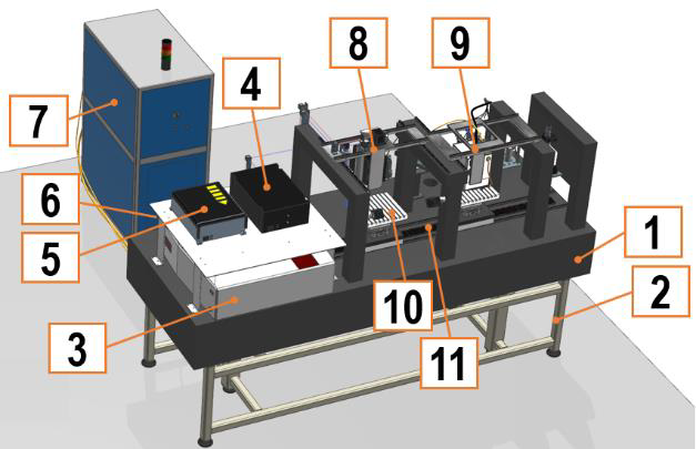
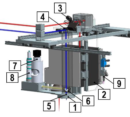
WISE machine configuration is shown in Fig. 12. The basement of machine (1), made of super-stiff granite, serves as the foundation for the entire structure. This natural vibration-damping material is supported by a metal structure (2), which is specifically designed to isolate vibrations and prevent any positioning errors during process execution. The basement is divided into 4 sectors. The first hosts the fs laser (3) and the blue CW diode laser (4) sources, along with the ns laser (5). The ns laser is close to the blue laser, allowing a more effective connection of the fiber to the optical combiner (6). The IR CW laser (7) is located behind the cabinet, outside the basement, and, together with the ns laser, features an optical fiber output which is connected to the optical combiner, located on the basement and designed to couple all the IR laser beams in the optical chain. The second sector is dedicated to all the laser-based processes, while the third is to the DALP process. Both sections feature a granite structure with a three-axis DoF gantry system enabling process heads (8) for the laser station and (9) for the DALP station) to move in X, Y, and Z directions. These two sectors cover a total working volume of 250x250x200 mm3 (X, Y, Z) providing adequate space to complete the tasks required by WISE products. Finally, the last sector hosts the sensing equipment for precise product and process assessment. The working table consists of two rotational axes (10). Depending on the process planning, the axes system moves between the two processing stations and the sensing system thanks to linear moving shuttles (11). As shown in Fig. 13, the machine is enclosed in an
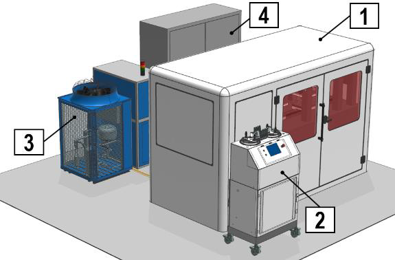
external cabinet (1) to ensure operator safety by blocking dangerous laser reflections. Auxiliary systems, such as a DED powder feeder (2), a chiller unit (3), and an electrical cabinet (4) containing essential power supplies, drivers, and electric equipment, are situated outside the enclosure.
i) Laser sources
WISE will integrate four different laser sources that will be exploited for the manufacturing of the WISE highcomplex products. This photonic equipment will be developed and integrated by the WISE project partners PA, AMPL, POLITO, and ALITE.
| Wawelenght | CW/Pulsed | Pulse duration | Power | Propagation mode | Application |
| IR (1070 nm) | CW | – | 6 kW | Fiber | DED with Hybrid Laser |
| BLUE (450 nm) | CW | – | 600 W | Free-space | DED with Hybrid Laser |
| IR (1064 nm) | Pulsed | 100 ns | 500 W | Fiber | Laser polishing |
| IR/Green (1030/515 nm) | Pulsed | 300 fs | 300 W | Free-space | Ablation and 2PP |
IR CW Fiber laser. High deposition efficiency and high DED build rates will be ensured by a 6 kW IR fiber laser provided by PA. This laser source boasts an M² factor of under 1.1, and uniform radiation absorption that yields a superior melt pool formation and quality. The emitted laser power will be internally split into two different output fibers. The first one will be connected to the combiner mounted on the granite basement and delivered by the optical chain to the DED head. The second one will be connected to the DALP head to preheat the surfaces based on the
requirements of nanocoatings application.
Blue CW laser. To enable high-quality HR metal DED processing, the hybrid laser solution will incorporate a blue diode laser source developed by ALITE in collaboration with POLITO. This 600W solution will utilize three 200 W multi-emitter modules based on the latest generation of GaN single-emitters, each capable of emitting approximately 10 W. To ensure high-level performance, the output of each chip will be separately collimated along two orthogonal axes using micro-optical components, ensuring precise positioning to deliver effective thermal dissipation.
Maintaining the beam parameter product (BPP) below a target value of 3 mm mrad will be fundamental to achieve optimal coupling efficiency. However, the proprietary architecture patented by ALITE will achieve an unprecedented BPP of 3 mm mrad for each module, corresponding to 12 TW/(sr m2) radiance.
Femtosecond Laser. Precise and efficient surface functionalization and 2PP are achieved by a 300 W fs laser developed by AMPL. Using an advanced slab amplification system, high-power pulses are generated with a duration of 400 fs and a repetition rate of up to 50 MHz. The fs laser is coupled with the FAST system, thus ensuring high position accuracy together with extremely high scan speed. With peak powers in the terawatt range, the laser system delivers highly localized material removal or modification with no heat affected zones, providing high-quality results compared to traditional laser systems.
Nanosecond Laser. For the polishing of the additively manufactured surface, long pulses are necessary to enable the selective melting of small portions of material and reach a surface roughness Ra < 0.2 μm. The ns ytterbium fiber laser module provides average output power up to 500 W, with MHz repetition rates, resulting in MW peak power pulses, necessary to obtain localized melting without material ablation.
(ii) Optical chain
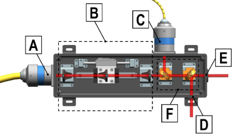
IR Laser Beams combiner and optical chain. The combiner, shown in Fig. 14, couples various IR laser beams into the same optical chain, which are then delivered to station 1 head. The output fiber of the IR CW laser is connected to the combiner via a QBH connector (A). A 3-elements motorized beam expander/reducer (B) enables adjustment of the beam dimension with magnification power ranging from x0.2 to x2. The combiner has also a second QBH connector (C) for the IR ns laser input beam. The fs laser free-space beam enters through the aperture (D). To combine all IR beam sources into the output aperture (E), two mirrors (F) featuring different surface coatings on each face are employed. The output beams are conveyed to the station 1 head by two HR mirrors positioned on the gantry structure.
Blue optical chain. The blue laser beam is delivered to the station 1 head by an optical chain, parallel to the IR one, constituted by 4 mirrors with HR coating @45deg for the 450 nm wavelength.
(iii) Station 1 head
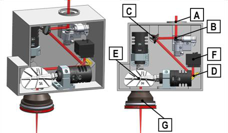
The optical chain delivers the different laser beams to the station 1 head (shown in Fig. 15), which consists of the DED head (1) and the FAST unit (2). The two modules are mounted in parallel on a linear stages system, integrated on the gantry structure. As first element of the head, a 2-position motorized mirror (3) can switch its position in order to direct the laser beam toward the DED head or the FAST unit depending on the process to be executed.
- The fs laser and ns laser beams are transmitted to the FAST unit to perform highly efficient beam shaping and scanning for ablation, 2PP
and polishing applications The mechanical axes movement will be interpolated with the scanner ones to create an infinite field of view
(IFOV) on all the machine’s total working volume to get increased productivity, improved accuracy, and greater flexibility in the design and
production of complex parts. - The IR CW beam is reflected towards a dichroic mirror (4), where it is multiplexed to the blue beam, enabling the use of a hybrid source for the additive manufacturing of WISE semi-finished parts. A special IR/blue coated spherical lens (5), with a focal length of 35 mm, focalises the beam in the convergent point of the head nozzles. An additional dichroic mirror (6) will reflect the radiation emitted during the process to an ultrafast camera (7) and a pyrometer (8) for inline monitoring. All the optical path will be protected from the powders in the machine with sealed tubes. As last element, a pneumatic precision 2PP photopolymer dispenser (9) is necessary to eject the precursor resin on the surfaces that needs a polymeric coating.
(iii-a) FAST Unit.
The FAST unit model is shown in Fig. 16. The collimated beam of the IR sources enters the FAST unit from the input aperture (A) and is directed towards the first (input) scanner (B). This scanner is designed to scan the overall DMD surface (D) at high and uniform speed. A HR mirror
(C) is inserted between the scanner and the DMD to efficiently steer the beam, and compact the unit design. A DMD is a MEMS consisting of millions of tiny switchable mirrors and is one of the key components of the FAST unit. Each mirror can be independently switched to + 45⁰ or – 45⁰ with respect to the surface normal. With the proper setup of the scanning trajectories, the scanning speed can reach over 20 m/s, which will ensure complete scanning of the DMD in less than 20ms. The system includes a profiling camera (F), which allows to acquire the “complementary image” of the arbitrary userdefined beam shape, and thus to implement an AI-based calibration and control apparatus that will constantly control the beam shape and quality. The overall working area will be scanned in successive steps, projecting the laser images
obtained with the DMD. After the FAST unit, a f-theta lens (G) is positioned to focus the IR shaped beam exiting from the scanner, with a working distance of 97.8 mm and an 80×80 mm2 scan field, which guarantees the telecentricity of the system.
(iii-b) DED head.
The DED head is located at the end of the optical chain and is responsible for feeding the AM process through a constant powder flow and shielding the melt pool from oxidation, preventing part degradation. The solution will implement a multi-nozzle deposition head equipped with four high-precision nozzles engineered to manage very collimated powder flow. The nozzles solution will be interchangeable and scalable for a wide range of deposition rates, ensuring a high powder density at the laser focus and guaranteeing high deposition efficiency. To improve part structural quality and prevent surface deterioration, the WISE DED head will also feature a Shielding system, which generates a gas bell shape (i.e., Argon) enveloping the melt deposition area and ensuring a content of O2 < 0.7%. The shielding system will be equipped with special sensors to constantly detect and control the O2 content in the shielded area.
(iv) Station 2 head.
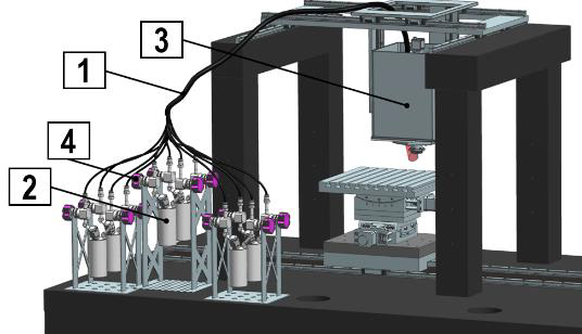
The Station 2 head (Fig. 17) is dedicated to the DALP process. To maximize the gases thermal stability, the precursor and reactant gas bubblers (1) are positioned right behind the gantry structure, also facilitating their replacement through the cabinet. The gas system contains six bubblers (three for precursors and three for reactants). Precursor/reagent vapours are transported from the bubblers to the head (2) via a Carrier gas. The DALP deposition head consists of four micro scale nozzles in pure silica. To perform a proper atomic deposition, the substrate needs a constant preheating temperature between 200-300 °C, realized by an optical fiber, exiting from a second output of the IR CW laser source, integrated close to the DALP head nozzles, thus exploiting the emitted laser beam to effectively heat precise surface areas to the correct
temperature to perform the process. This solution will overcome the current drawbacks that conventional bottom-up heating systems face in preheating massive and geometrically complex parts. Moreover, a closed-loop control system will adapt the incident laser power based on surface measurements inputs detected by a thermal camera.
(v) Powder feeder.
To enable the realization of high-quality composite materials (e.g., CCMs), an innovative powder feeding system is integrated into the WISE machine. The developed SUPSI solution will enable accurate and high-quality deposition for both low and high DED regimes: for micro deposition involving small laser beam size (e.g. 0.2 mm), the powder feeder will ensure highly stable powder supply enabling powder feed rates ranging between 1 g/min and 10 g/min, while for massive depositions involving large laser beam (e.g. 5 mm) the feeding system will ensure reliable powder feed rates up to 150 g/min. Based on the required mixing of the metal alloys and on the need to modulate the powder focus based on the laser beam spot size, the Carrier gas flow (i.e. Argon) will be adapted from 4 l/min to 25 l/min, guaranteeing high powder densities at the melt pool for any process regime. Highly stable and focused powder flows, as well as an accurate regulation of the stoichiometry of the powder-gas mixture, will be achieved based on a set of flow and powder sensors across the entire powder-gas supply system in order to accurately measure and control the process parameters (i.e. Carrier gas flow, Shielding gas flow, and powder mass flow).
(vi) Sensing system.
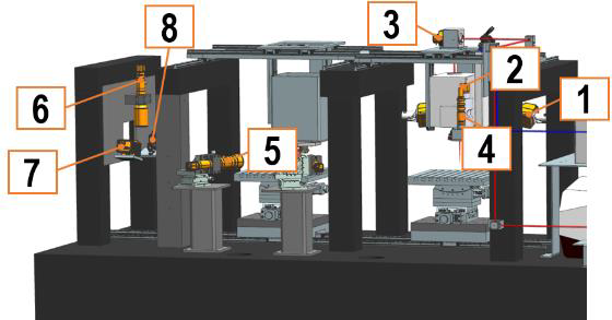
The WISE solution will be developed to achieve the goal of ‘firsttime-right’ production. To fulfil this purpose, both WISE workstations will be equipped with an advanced sensing system that will allow for the acquisition of reliable and accurate data (e.g. melt pool temperature, melt pool brightness and size, ablated surface temperature, morphological and topological analysis of surface structures, etc.). The sensing system will consist of in-line sensors, that will acquire data while the process is running, and offline sensors, that operate when the process is stopped in the dedicated station. The following table outlines the purpose of such sensors and Fig. 18 details their position within the machine architecture.